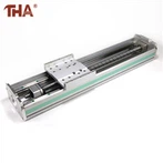
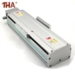
Anwendung der Linearführung in Werkzeugmaschinen
Das Führungsschienensystem ermöglicht der Werkzeugmaschine eine schnelle Vorschubgeschwindigkeit. Eilgang ist bei gleicher Spindeldrehzahl ein Merkmal von Linearführungen. Linearführungen haben wie Flachführungen zwei Grundelemente; Eines als Führung ist ein festes Element und das andere ist ein bewegliches Element. Da es sich bei der Linearführung um ein Standardbauteil handelt, ist es für Werkzeugmaschinenhersteller. Es muss lediglich die Ebene einer Montageschiene bearbeitet und die Parallelität der Schiene eingestellt werden. Um die Genauigkeit der Werkzeugmaschine zu gewährleisten, ist natürlich ein geringes Abkratzen des Betts oder der Säule wesentlich. In den meisten Fällen ist die Installation relativ einfach.
Compared with flat guide rails, the cross-sectional geometry of linear guide rails is more complicated than that of flat guide rails. The reason for the complexity is that grooves need to be machined on the guide rails to facilitate the movement of sliding elements. The shape and number of grooves depend on the machine tool to complete. Function. For example: a guide rail system that bears both linear force and subversive moment is compared with a guide rail that only bears linear force. The design is very different.
There is no intermediate medium between the moving element and the fixed element of the linear guide, but a rolling steel ball. Because the rolling steel ball is suitable for high-speed motion, has a small friction coefficient and high sensitivity, it can meet the working requirements of moving parts, such as the tool holder and carriage of the machine tool. The basic function of the fixed element (guide rail) of the linear guide system is like a bearing ring, and the bracket for mounting the steel ball is shaped like a "v". The bracket wraps the top and both sides of the rail. In order to support the working parts of the machine tool, a set of linear guide has at least four supports. Used to support large working parts, the number of brackets can be more than four.
When the working parts of the machine tool move, the steel balls circulate in the groove of the bracket, and the wear of the bracket is distributed to each steel ball, thereby prolonging the service life of the linear guide. In order to eliminate the gap between the bracket and the guide rail, the preload can improve the stability of the guide rail system and the preload can be obtained. It is to install an oversized steel ball between the guide rail and the bracket. The diameter tolerance of the steel ball is ±20 microns, with 0.5 micron increments. The steel balls are screened and classified and installed on the guide rails respectively. The size of the preload depends on the force acting on the steel balls. If the force acting on the steel ball is too large, the steel ball will withstand the preload for too long, which will increase the movement resistance of the bracket. There is a balance problem here; in order to improve the sensitivity of the system and reduce the movement resistance, the preload must be reduced accordingly, and in order to improve the movement accuracy and the retention of precision, it is required to have sufficient preload negative numbers, which are contradictory two. aspect.
If the working time is too long, the steel ball starts to wear out, and the preload on the steel ball starts to weaken, resulting in a decrease in the movement accuracy of the working parts of the machine tool. If you want to maintain the initial accuracy, you must replace the rail bracket, or even replace the rail. If the rail system has a preload effect. The accuracy of the system has been lost, and the only way is to replace the rolling elements.
Das Design des Führungsschienensystems strebt danach, die größtmögliche Kontaktfläche zwischen dem feststehenden Element und dem beweglichen Element zu haben. Dies verbessert nicht nur die Tragfähigkeit des Systems, sondern das System kann auch der Stoßkraft widerstehen, die durch intermittierendes Schneiden oder Schwerkraftschneiden erzeugt wird, die Kraft weit verteilen und die Tragfähigkeit erweitern. Der Kraftbereich. Um dies zu erreichen, gibt es verschiedene Rillenformen des Führungsschienensystems, und es gibt zwei repräsentative, eine wird als Gedai-Typ (Spitzbogentyp) bezeichnet, die Form ist eine halbkreisförmige Verlängerung, und der Kontaktpunkt ist der Apex; Die andere ist eine Kreisbogenform, die auch die gleiche Rolle spielen kann. Unabhängig von der Art der Struktur gibt es nur einen Zweck und streben danach, einen größeren Rollstahlkugelradiuskontakt mit der Führungsschiene (festem Element) zu haben. Der Faktor, der die Leistungsmerkmale des Systems bestimmt, ist: Wie die Wälzkörper die Führungsschiene berühren, was der Schlüssel zum Problem ist.